...
Widget Connector width 700 url https://www.youtube.com/watch?v=sXQPAysETrQ height 400
An overview of working with Feature Selector.
Description
The Feature Selector node allows you to generate generates a grayscale mask from a selection of pixel regions of similar color (referred to as ‘features’) features in the input texture.
The node automatically identifies a set of such defines a feature as a region of pixels. The node identifies features in the input texture . There is no way to automatically. You cannot manually define a feature area, but you can fine-tune the automatic feature definition behavior by adjusting the node properties - specifically Granularity, Color, Regularity, and Smoothness. See more on properties and their effects in use the node properties to influence how the node identifies features. For a list of available properties and what they do, see the Properties section below.
You can To create a selection from one or more features by bringing , you can bring the node into the 2D Viewport and using use the node’s 2D Viewport Overlay. By default, the node creates one selection region, known as a segment. You can add and edit up to 3 segments, each containing a different selection region.
Alternatively, you can let ArtEngine automatically create segments with selections by using AI Assist with at least two mask inputs.
When you execute the node, it creates and outputs a black and white mask . All pixels within texture for each of the segments. The white pixels in this texture represent the features you selected are colored white, and the rest are colored . The rest of the texture is black.
Selecting features in the 2D Viewport
Here are the steps to creating and adjusting a From the features the node identifies, you can select the ones to include in the output mask. To create and adjust a feature selection:
- Bring the Feature Selector node into the 2D Viewport.
- The 2D Viewport displays an overlay , where that separates the input texture is segmented into regions separated surrounded by black borders. Each region represents a single selectable feature. You can change the overlay color and opacity in the node properties.
- To select a feature, left click (LMB) on its region in the viewport. The region fills with the Overlay Color (teal by default, this is teal), which indicates that it is currently selected. To change the color and opacity of the overlay, see Properties.Add
When using the 2D Viewport Overlay, you can further manipulate the selection in the following ways:
- To add more features to the selection
...
- , hold Shift and click on additional regions.
...
- To remove features from the selection
...
- , hold Ctrl and click on a region you want to de-select.
- To invert the selection, use the Invert button in the node properties.
...
- For a full list of shortcuts
...
- , see 2D Viewport controls.
Using Lasso Selection
An alternative way to select features is by using the Lasso Selection tool. This allows you to draw a polygonal lasso by placing multiple points in the 2D Viewport. When you close the lasso, the node creates a new selection from the features that are inside the lasso area.Here are the steps to using
Note: The Lasso Selection tool only selects features that are completely enclosed within the lasso area.
To use Lasso Selection:
- With the Feature Selector node in the 2D Viewport, press the L key.
- A lasso icon appears in place of your mouse cursor. This indicates that the Lasso Selection tool is active. You can press the L key again to deactivate the tool.
- To start a lasso selection, left click the point in the 2D Viewport where you want the lasso to begin.
- Add To add more points to the lasso by left clicking , click elsewhere in the viewport.
- Close To close the lasso by clicking , click the first point you placed.
- The By default, the node creates a selection from features inside the lasso area. You can use the Shift and Ctrl keys to add and remove the lassoed area from an existing selection, respectively.
2D Viewport Controls
Below is a complete list of shortcuts for working with the 2D Viewport Overlay.
| Action | Description |
|---|---|
LMBLeft-click | Select a single feature by clicking (left-click on its region in the viewport). |
Hold LMB Left-click and drag | Select one or more features by dragging (left-click and drag over their regions in the viewport). |
CTRL Ctrl + LMBleft-click | Deselect a single feature. |
CTRL + hold LMB Ctrl + left-click and drag | Deselect one or more features. |
SHIFT Shift + LMBleft-click | Add a single feature to the current selection. |
SHIFT + hold LMB Shift + left-click and drag | Add one or more features to the current selection. |
L | Press to activate or deactivate the Lasso Selection tool. |
Generating a mask from a selection
Once you have a selection ready, you can create a new mask from it by executing the node.
...
Automatic selection using AI Assist
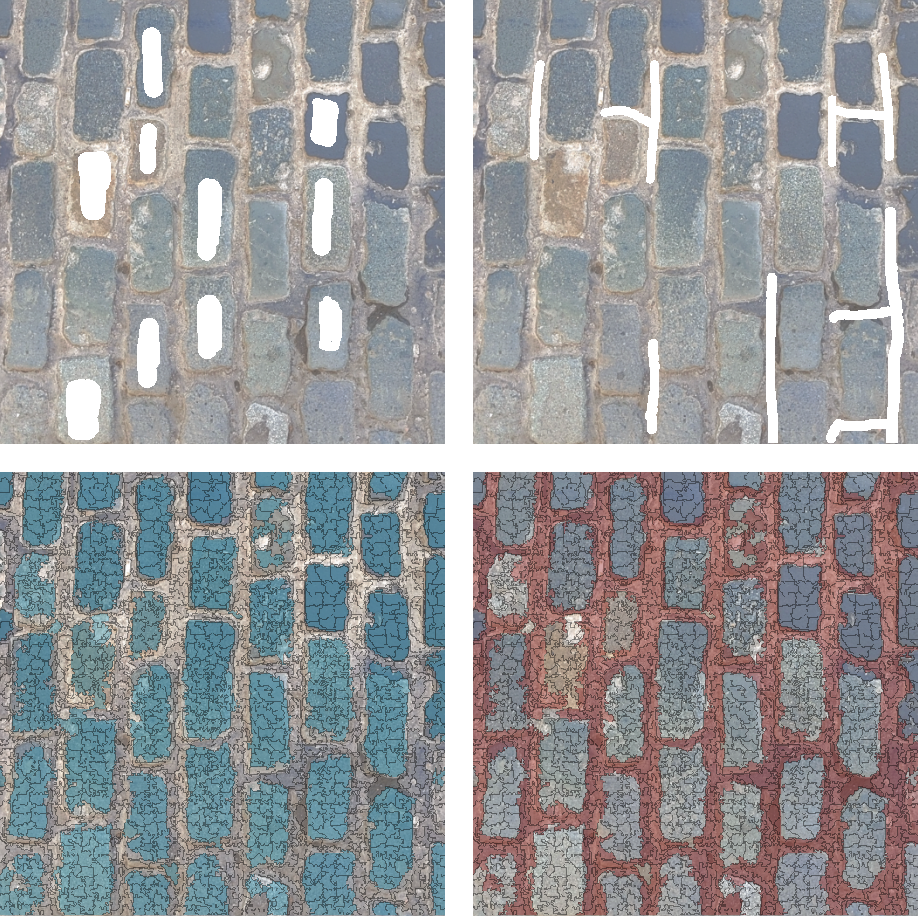
Two masks (above) and the corresponding segments identified by AI segmentation (below).
Feature Selector can automatically identify similar regions in the input image, and create selections from them, placing each selection into a different segment. To determine how similar any two features are, the algorithm uses a combination of surface texture and color influence. You have a degree of control over each of these in the Properties window.
To identify different regions, the AI segmentation algorithm requires at least two mask inputs in addition to the main input image. Each mask should roughly indicate a part of the input image that you want the algorithm to deem as a separate region. The mask does not have to be precise, nor does it need to cover most of the image. A few rough brush strokes are often enough for the algorithm to work.
For example, in a texture with bricks, you might use one mask to paint over a couple of bricks, and another mask to paint over some of the mortar.
To use AI segmentation:
- Create at least two masks of the main input image. Each mask should roughly indicate a different region of the image. For example, the masks may indicate two areas of different color or surface material.
- Connect the masks to the Mask1 and Mask2 inputs of Feature Selector.
- In the Properties window of Feature Selector, enable AI Segmentation by ticking the box next to it.
- (Optional) Change the Feature Bias and Texture Weight properties to fine-tune the algorithm behavior. Descriptions of these properties are available in the reference section at the bottom of the page.
- Execute the algorithm by pressing the AI Assist button.
- Once segmentation is complete, review the new segments created by the algorithm. For more information on working with segments, see the reference section.
Generating a mask from a selection
To create a new mask, select the features you want to include and execute the node.
The Feature Selector node outputs the mask as a texture, which you can export or use elsewhere in the Node Graph of your project.
...
| Node category | Paint |
|---|---|
| Node execution style | Manual |
Ports
| Input Name | Input Type | Description |
|---|---|---|
| Input | Bitmap | The input texture from which you want to select features from. |
| Mask1, Mask2, Mask3 | Bitmap (Mask) | The masks that Feature Selector uses for AI-assisted selection. |
| Output Name | Output Type | Description |
|---|---|---|
| Segment 1-3 | Bitmap (Mask) | The output mask texture, which contains a representation of the selection. |
Properties
...
| Property/Setting | Description | |
|---|---|---|
Granularity | Control Controls the size and number of features which that the node breaks the input texture is broken into. Higher values produce morea higher number of, smaller features. | |
| Color | Control Controls how strongly color similarity influences the formation of feature regions. At higher values, the node is more selective in judging colors as similar. As a result, the feature borders follow different colors more precisely. | |
Regularity | Control how blocky the features are. At higher values, features maintain a primarily square shape and are more similar to each other in size. | |
Smoothness | Control Controls the smoothness of feature region borders. At higher values, the node avoids adding many small pixels along feature borders, effectively smoothing them out. | Overlay Color | Set the color of the selection
AI Segmentation
This part of the Properties window contains settings that are specific to AI-assisted segmentation.
| Property/Setting | Description |
|---|---|
| Feature Bias | This property influences the segmentation behavior based on the surface texture of the input. The available options are:
|
| Texture Weight | Control the balance of influence between surface texture and color during AI segmentation. Higher values place more importance on surface texture, and lower values place more importance on color. |
| AI Assist | Click this button to execute AI Assist when you connect two or more masks to the Feature Selector node. |
Segment settings
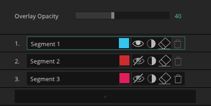
Below the AI Segmentation settings is a list of selection regions, or segments, present in the node. You can edit each of the segments and add or remove features from them using the 2D Viewport. The Overlay Opacity controls the opacity of the Feature Selector overlay in the 2D Viewport.
...
Overlay Opacity
...
Each segment in the list has the following controls, listed in the order that they appear:
- Segment Name - determines the name under which the segment appears in the outputs of Feature Selector.
- Segment Color - controls the color of the segment overlay in the 2D Viewport.
- View Segment - enable to display the chosen segment in the 2D Viewport and enable editing for its selection region.
- Invert Selection - invert all selected features in the segment.
- Clear Selection - remove all features from this segment’s current selection.
- Delete Segment - remove this segment and its selection from the outputs of the node.
The Add button below this list adds another segment to the list, up to a maximum of 3.